Quantcast
Channel: Data converters forum - Recent Threads
Viewing all 5988 articles
Browse latest View live

ADS1278EVM-PDK: Evaluation board seems to boot ok, but no measure is done

$
0
0

Part Number: ADS1278EVM-PDK

Hello,

We have purchased ADS1278EVM-PDK evaluation board and tried to test it connected to computer using ADCPro software.

It seems it recognizes the board properly and boots MMB0 DSP ok, but when trying to acquire it shows nothing.

The steps we have done:

1. Prior to connect it, we read ADS1278EVM user’s guide (also ADCPro guides), and followed all steps, checking that all jumper configuration was as default. Then, we installed software required (including driver).

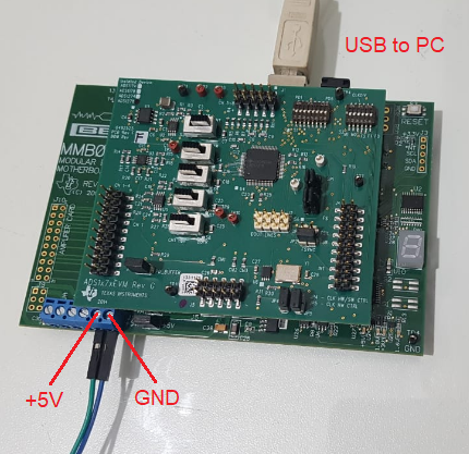
After that we connected power (+5V) as it is described on ‘ADCPro Hardware and Software Installation Manual’:

With board powered on, we connected USB to computer. Power and USB were the only connections done to the board, as shown on following picture:

2. We run ADCPro software and selected from menu: EVM ADS1278EVM.

After some (green) messages it shows ‘Connected to EVM’, and I see 1-2-7-8 sequence on 7-segment display of MMB0.
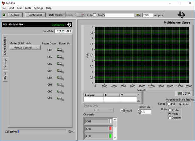
 

3. Select from menu: Test MultiScope.

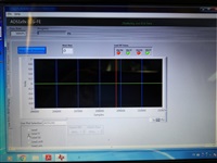
4. Clicked on ‘Acquire’, and after some fast green text messages it shows ‘Connected’, but no measure is shown:

I also tried by clicking on ‘Continuous’, but it keeps in the following state until I click on ‘Continuous’ again:

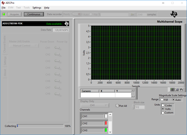
I’ve tried changing Clock Source, from PLL to ‘On-board’, and operating mode, but always same result, no measure is shown:

All four voltage leds indicators are turned on in MMB0 (+5V / +1.8V / +3.3V / +1.6V).


After doing a few tries, by reconnecting USB, power off/on, etc. I noticed that ADS1278EVM daughter board was hot, so I measure current consumption with daughter board connected and disconnected:

  • MMB0 only (ADS1278EVM disconnected): 190 mA
  • MMB0 with ADS1278EVM connected: 840 mA


Maybe I am wrong, but I think that the current consumption difference that appears while connecting EVM card is very high for this board, so I suspect that there is something wrong/damage with the ADS1278EVM daughter board.

Or am I doing anything wrong?

Thanks for any help!

Best regards,

Alejandro Panelli


ADC12DJ3200EVM: What is the frequency response of the ADC with the EVM?

$
0
0

Part Number: ADC12DJ3200EVM

Hello,

On page 1 of the datasheet for ADC12DJ3200 (SLVSD97) there is a plot of the scalar frequency response of the ADC titled "ADC12DJ3200 Measured Input Bandwidth". Does this plot include the response of the EVM or is it just the ADC12DJ3200 IC by itself? Are there measurements of the frequency response of the ADC with the EVM?

Thanks,

Alex

ADS112U04: Schematic review

$
0
0

Part Number: ADS112U04

Hi Sirs,

Sorry to bother you.

Attached is our schematic.

Can you help us to review it?


  1. Our UART interface are going with 1.8V.
  2. AIN0~AIN4 are going to detect voltage from 1.6V~3.6V
  3. RESET pin is active low. What’s reset pin’s high voltage? 1.8V or 3.3V?

Schematic:

(Please visit the site to view this file)

DAC8771: Resistive Load in current output mode

$
0
0

Part Number: DAC8771

Hi team,

I got 2 questions from the customer.

1. The datasheet mentioned resistive load in current output mode. In my understanding, All except +/-24mA means the current output is 0 mA - 24 mA; 3.5 mA - 23.5 mA;0 mA - 20 mA; 4 mA - 20 mA. Is it correct?

2. Is there minimum resistive load value in current output mode?

Regards,

Yoshi

ADS114S08: check the ads114s08 Internal 2.5-V reference

$
0
0

Part Number: ADS114S08

I used ADS114S08  to measure the voltage. I configer ads114s08 as Internal 2.5-V reference (REF = 0x0A)  as Vref

I need make sure that Internal 2.5-V reference is ok, but I don't know how to check the Reference voltage(Internal 2.5-V) is ok or no.

Can I reading registers to get the Internal reference status?  how to config the ads114s08 registers ?

thank you !

ADS5400: TI ADC control software

$
0
0

Part Number: ADS5400

Hello,

Could you please tell me where could download the TI ADC SPI control software?  The ADC5400 EVM user's guide describes that it use the TI ADC  SPI software, but I am not sure if our customer could download on TI website directly.

http://www.ti.com/cn/lit/ug/slau293/slau293.pdf

Best regards

Kailyn

ADC32RF80EVM: can‘t download

$
0
0

Part Number: ADC32RF80EVM

I have an ADC32RF80-EVM development board and I need to download the ADC32RFxx EVM GUI Installation software from the website. However, each time the software starts to download for a few minutes, it will display "Failed - need to be authorized". Click and re-download, but the same phenomenon will appear in a few minutes. Caused unable to download. How can I download the software?thanks

ADS1120: RRDY behavior

$
0
0

Part Number: ADS1120

Hi team,

My customer considers to use ADS1120 and provided some questions.

  1. In case of single shot mode, the customer read data by RDATA command then DRDY becomes high.
    After that, will DRDY never go low if no START/SYNC command is sent?
    (Will DRDY keep high unless START/SYNC command is sent?)
  2. in section 8.5.5, there is description that ". Figure 66 shows an example for sending a WREG command to write two configuration registers while reading conversion data in continuous conversion mode. After the command is clocked in (after the 32nd SCLK falling edge), the device resets the digital filter and starts converting with the new register settings.".
    Does sending WREG command start conversion even in case of single shot mode?

Best regards,

Shota Mago


AFE5401-Q1: Power-on to Reset Delay Time

$
0
0

Part Number: AFE5401-Q1

Hi Team,

There are two questions about AFE5401 timing requirements, could you please help explain? Thanks!

1. Why does the power-on reset delay t1 have typical value rather than minimum value in datasheet? 

2.  Figure 2 describes the reset timing requirements, does it mean that all the four power supply(AVDD18, DVDD18, AVDD3, DRVDD) should be at least t1 before reset? Is there any sequence requirement for the four power supply?


Best Regards!

Hao

ADS131M04: Please suggest 16bit solution

$
0
0

Part Number: ADS131M04

Hi sir, 

We suggest ADS131M04 to our customer. Basically, it can meet customer's requirement, but customer still wants to know if we have 16bit solution which would be more cost effective than ADS131M04 24bit. Thanks a lot!

BR, 

Sean Liao

ADS125H02: ADS125H02 calibration guide

$
0
0

Part Number: ADS125H02

Hi 

Do you have ADS125H02 calibration guide?


(1) for ADC calibration,DATASHEET Page41~44 , how to setting or calibration?


(2)for ADC digi filter,DATASHEET Page.33-38 how to setting or calibration?


Eric

ADS1292RECG-FE: Cannot detect any signal

$
0
0

Part Number: ADS1292RECG-FE

Hi,

I meet problems with the ADS1292ECG-FE. I didn't have DB9 to ECG connector, so I soldered the DB9 wire to a ECG lead as I showed in the picture. I ’m sure that all of them are connected following "Figure 46. DB9 ECG Connector Pin Outs" in user's guide and there's no short between those wires. However, I cannot detect any signal when I connect the connector to electrode on my body.


How to solve this?

Thank you!

ADC12J1600EVM: changing input voltage range when used with TSW14J56

$
0
0

Part Number: ADC12J1600EVM

Hello,

I am using the ADC12J1600EVM together with the TSW14J56EVM. 

In my application I need to operate the ADC12J1600 at its minimum voltage range of 500mV. I have changed that parameter in the GUI under the window Control/Gain and Offset, and then clicked Program Clock and ADC in the EVM window. In this way I saw that the voltage range is now set to 500 mV.

My problem is that when looking into the HSDC Pro GUI this does not to change anything compared to the default setting of 725mV. This is because when measuring the RMS of a signal in input in the ADC it is the same (both in codes and voltage) in the case of 500mV and 725mV. I was expecting to see of course the same voltage RMS for the same input signal, but this would be different when expressed in codes.

It seems to me that I might be missing some steps in the procedure of changing the input voltage range.

Would it be possible to have more info on how to have this set properly, or would it be possible to be directed to the right location in the user guide where this is explained? I have been looking already but without finding any info.

Kind regards,

Francesco

ADC12DJ3200: working of time-stamp signal

$
0
0

Part Number: ADC12DJ3200

Customer would like to know the working of time-stamp signal of ADC12DJ3200.

I want to know the operating frequency of time-stamp signal.

Whether the frequency of time-stamp signal varies with sampling frequency.

OR 

Is it just logic i.e., time-stamp only required to be made high(1) or low(0) for all sampling frequency range.

I am planning to use Si5330 buffer in HCSL mode for interfacing FPGA and ADC12DJ3200 for meeting the common mode voltage and swing requirement of time-stamp signal pins.

The thing is Si5330 supports frequency range of 5-250Mhz only.

So if I use Si5330 for time-stamp pins of ADC12DJ3200, then I need to operate time-stamp signal in the frequency range of 5-250Mhz only.

ADS1158: ADS1158 -- Circuit Design

$
0
0

Part Number: ADS1158

Hi,

We have used ADS1158 in one of our project which is configured as alternate current and voltage input channels ( 8 current and 8 voltage input). The reference design as shown below

Now I am using first input channel for 0-10V analog voltage and second channel for 4-20mA analog current.

Recommend me what to do with left over channels ( should i leave it floating ) ?

Please suggest any ADC with two channel compatibility for the same design considerations ( input voltage and input current design as shown in above figure )


DAC3282EVM: Double frequency output

$
0
0

Part Number: DAC3282EVM

We are trying to evaluate the DAC3282 using a DAC3282 Evaluation board and a TSW1400 pattern generator.

We have made the modifications in section 4.1 of the user guide for the eval board for output from the DACs.

In the MasterDAC3282GUI_v2p1.vi we can read the temperature of the DAC.  However, this software regularly loses contact with the Eval board which is not confidence inspiring.  We have set the interpolation to 1x

If we then open the High speed data convertor software, generate a single tone at 1 MHz (moved slightly to have an integer number of cycles in the sample window) and send this to the DAC, we get a 2 MHz sine wave on our high speed scope, why is this?

regards,

David Cruickshank

ADS131E08S: Output wraps between 32768 to -32768

$
0
0

Part Number: ADS131E08S

Hello Team,

Currently, we are using the ADS131e08 chip, for measuring the resistance. ADS131e08s chip is connected to a microcontroller, communicate with SPI protocol. ADS131e08s acts as a slave and microcontroller act as a master. ADS131e08s and microcontroller communicate with each other with SPI protocol.
Using the RDATAC command, we are able to get the readings from the ADS chip, but the output is getting wrapped at a positive value of 32768(16 bit) and the negative value of -32768.


By default in the CONFIG1 register, DR[2:0] bits is set to 4, which should result in 24-bit output, but it always results in the 16-bit output. We also tried to change DR[2:0] bits in CONFIG1 register, but it didn't change the result. We are able to measure the correct data rate, for corresponding DR[2:0] bits value.

Could someone please tell, how it needs to be corrected, so that output would be 24 bit.

I have also attached a  screenshot of wrapping for your reference.

Thanks in advance,
Best regards,
Chetan

ADS54J64: ADS54J64EVM input transformer concerns

$
0
0

Part Number: ADS54J64

Dear colleague,

Customer asks why we use 2 transformers in one channel?

And what What is the function of the resistor and capacitor network behind T9? Do we have a detailed description?

Thanks a lot!

Best Regards,

Rock Su

ADS131E08: ADS131E08 does not power up

$
0
0

Part Number: ADS131E08

Hi,

I'm using an ADS131E08 but I can make it to power up.

My application circuit is as follows:

SPI and RST_AD are also connected to microcontrollers, but they are High-Z right now.

When I measure VCAP1, it is 0.15 V. What can be happening?

Thanks!

ADS1278: ENOB and SNR in the case of a signal with an amplitude of 20 dB below the FSR.

$
0
0

Part Number: ADS1278

Hi team,

I received the following request from a customer I'm following. Could you assist?

###################################################################

The component will be used in HIGH SPEED mode with a fCLK of about 34 MHz with a VREF of 2.048V.

We want to calculate ENOB and SNR in the case of a signal with an amplitude of 20 dB below the FSR.

From page 6 of the datasheet I have the value of SNR and THD, but in the conditions described above (ie fclk = 27 MHz, VREFP = 2.5V): therefore the value of SNR and ENOB will be less than what I can calculate, since my fCLK (and therefore the sampling rate) are higher.

At a signal with -20dBFS, how much will these values be? I don't seem to have found details that allow me to calculate these quantities.

You can help me?

####################################################################

Regards,

Fabio

Viewing all 5988 articles
Browse latest View live


<script src="https://jsc.adskeeper.com/r/s/rssing.com.1596347.js" async> </script>